The basics:
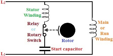
A 110 vac motor contains two windings: run winding and a start winding. The run winding keeps the motor going. But the motor, powered by the run winding, does not care if it is running CW or CCW. If one applies power to the run winding, it will run but the direction is simply dependent upon when exactly in the the power is applied (upper or lower portion of the 110 vac sine wave) or if it is already spinning. If somehow you begin spinning the motor and then apply the 110 vac on the run winding, it will continue to spin in that same direction.
Giving it a little extra spin energy on starting and nudging it in one direction or the other is the purpose of the start winding. The start winding provides a field that is slightly out-of-sync with the field of the run winding. As a result, it provides a little field push in one direction. If the voltage provides a field is slightly leading the run winding field, the motor will tend in that “forward” direction. If the voltage provides a field slightly lagging the run winding field, the motor will tend in the “reverse” direction. Once started, the start winding is not needed and power is removed from the winding.
The winding does not move, obviously, but the current through the winding will slightly lag or lead the current in the run winding. There is a capacitor in series with the start winding. The capacitor puts the start winding’s current — which is what produces the field in the motor — slightly out of phase with the applied 110 voltage and out of phase with the current in the run winding. Thus there is an additional field in the motor that is out of phase with the run field. And this additional field provides the needed extra asymmetric nudge in one or the other start direction.
In the stopped position, there is spring actuated disk on the motor shaft which presses on a switch on the motor body and closes the switch contacts. As the motor spins up, centrifugal forces move the disk down the motor shaft, away from the switch, and that allows the switch to open. Thus the switch is in the closed position when the motor is stopped. When the motor starts, the disks moves away from the switch and then switch opens. When the switch is closed (motor stopped), the start winding circuit is energized. When the motor switch is open (motor running), the start winding circuit is open and unenergized.
(ref: motor info )
Summarized:
- @ 0 RPM, i.e. on start: both run and start circuits are energized
- @ running RPM: run circuit is only winding energized
(good summary )
What the reversing switch should do:
The switch should apply power to the run windings — without changing phase (110 vac wires) . The start winding needs the two 110 vac wires applied attached one way and then, to reverse, attached the other way.
So, from the motor need 4 wires — the pair from the run winding and the pair from the start winding. And ground, of course.
Switches:
The reversing switch is most commonly called a “barrel switch”. There are a lot of diagrams of how such a switch operates. The most common has terminals labelled #1 through #6. Note that terminal numbers will varry from switch manufacturer to manufacturer — there is no standard. They usually operate like this:
- When the switch is in either CW or CCW position, terminals #1 and #2 are connected.
- When the switch is in direction A position, #3 and #4 are connected and #5 and #6 are connected.
- When the switch is in direction B position, #3 and #6 are connected and #4 and #5 are connected.
Motor connection:
To use these switches, first run a jumper from #1 to #3.
From the motor, run four wires (A, B, C, and D). From the start winding-capacitor-switch: A and B. From the run winding: C and D. Connect like this:
Note that in this position, A and C are the red HOT side of the 110 vac. D and B are the NEUTRAL of the 110 vac.
In the other switch position:
In this position, the motor C and D are the same HOT and NEUTRAL (i.e. no change). However, the A and B have swapped!
The switch:
Switches are made by many manufacturers. The more expensive look like a barrel (Hubbel etc. $40 to $80). There is a cheap version that looks like a green box ($10). It is not very robust but may be appropriate for you application (no indication that it is NEMA or UL rated). There is slim documentation about this switch…so here is some info.
Looking internally, the switch has 10 terminals with only 6 of the terminals with screws for connection. There is a small drawing on the box.
For this switch, only 1, 2, 3, 4, 5 and 6 are marked at the positions where there is a provided screw terminal. I have marked the no-screw positions with an extra “x” and numbered them according to where their jumper connects. The numbers correspond to the narrative above.
This next drawing is how I connected the system. Note that in order to avoid placing two wires on a single terminal, I chose to add screws to position 3x and 5x.
Drum switch (Furnas and Hubbel)
The inexpensive green box switch from China is essentially a flat double-sided switch with a central post with tangs that open and close the switch. An alternative contstruction method is used for the “drum switch” wherein the central shaft moves contacts along a set of radial contacts. Furnas A14D is a common type. It is NEMA and UL rated (the green box shows no such rating info). Note that Siemens bought Furnas and the Drum Switch product linewas bought up by Hubbell. Bremas and Salzer is another common maker of this simple drum switch.
The wiring diagram and application info for the Furnas A14D is:
(from Hubbell catalog 4258, July 2010, Furnas Brand Class 58 Drum Controllers)
Note the internal connection diagram and the “Condensor Motor–4 Leads” diagram.
I have the Furnas switch. There were some problems so I took it apart. A very simple switch. Easy to clean. I removed the central brass screw and pulled out the piece with the connections screws and the contact tangs. There remained a black plastic ball attached to the handle and the box cover. I didn’t figure out how to remove this but decided it was not necessary for my repair. I washed the two pieces with a diluted mix of vinegar and a brush. The scorched/pitted tang contacts I smoothed with an emory board. Reassembly was easy and everything was just dandy after that.